Any sort of device that requires electricity also requires a conductor, i.e. an object that helps generate and deliver the electricity. Metal wiring (commonly in the form of copper or aluminum) is a great conductor, and depending on its size in diameter, will offer various levels of electricity. But – how do you indicate the right size for your electrical needs? This is where determining cable gauges comes into play. Keep reading to follow our cable gauges guide.
When referencing the “gauge” of a cable, this translates to the thickness or diameter of the wire. Fortunately, there are standardized systems in place to measure cables. The most popular is the American Wire Gauge (AWG) system. This system labels cable sizes numerically, and the size of the cable decreases as its gauge number increases. Moreover, the size doubles for every six-gauge number decreases. For example, a 0.144-inch cable is rated as 7 AWG. When you double that cable size (to 0.289-inch), it is rated as 1 AWG. However, a size 1 AWG is not the largest cable. The sizes above a 1 AWG are rated in consecutive zeros, e.g. 0, or 1/0 (pronounced “one aught”), 00 (2/0), 000 (3/0), and so on. An important note is that larger gauges are not usually formed as one single piece, but rather are formed in bundles with many small wires.
Vanair® offers an extensive line of Goodall® Engine Starting Systems cables in various duty levels, and these cable options range from 4 gauge to 4/0 gauge. Perfect for your engine starting needs, Vanair® cables come in industrial-duty, heavy-duty, standard-duty, and light-duty options, and are fit for a wide variety of applications. Our industrial-duty and heavy-duty cables are best suited for jump-starting large marine or diesel engines, semi trucks, and tractors, while our standard-duty and light-duty cables are ideal for smaller engine-starting applications, such as 12V systems like pickup trucks, service vans, small diesel engines, and cars.
Aside from the size of the cable, other factors are important to consider in selecting the correct gauge. These include resistance level, frequency, and amperage:
- Resistance
- The flow of electricity in an alternating electric current (AC) is impacted by the “skin effect,” which is a phenomenon in which the electrical current flows on the outer edges of the wire, rather than within the center of the wire. The resistance of electrical flow occurs the most within the center of the wire, therefore the greater the resistance, the greater the skin effect. As the size of the wire decreases, the resistance disproportionately becomes greater, and further increases frequency.
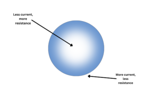
*Diagram of the skin effect. The white area in the center of the circle indicates the least amount of electrical current within a cable. The blue area on the outer edge of the circle indicates the greatest amount of electrical current within a cable.
- Frequency
- Frequency in electrical wiring refers to the amount of times a current switches from positive to negative per second, which is measured in hertz (Hz). Smaller cable gauges experience a greater frequency compared to larger ones.
- Amperage
- Amperage measures the electrical current within the wire, expressed as “amperes” or “amps”. Of course, the electrical current decreases as the size of the wire decreases. The less wiring available to deliver electrical currents, the less amperage is delivered.
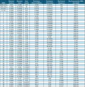
Below is a chart representing the measurements followed under the AWG Standard. Please note that these measurements are based on copper wire for its greater conductivity compared to other materials. The maximum frequency is based on 100% skin depth, meaning there is no resistance and electricity runs through the entire cable. Resistance levels apply Ohm’s Law per 1,000 feet and per kilometer. Ohm’s law describes the relationship between electrical current (I), voltage (V), and resistance (R). In this table, Ohm’s law represents the equation R= V/I.